Search Knowledge Base by Keyword
Getting Started
This article will cover the different heatmaps available in Verity, as well as pointing out the differences and advantages to each one.
Heatmap
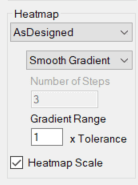
In the Verity Heatmap section, you can adjust several settings that affect which geometry the heatmap is calculated against, the type of gradient, step sizes, range, and the visibility of the heatmap legend. The heatmap display will be set to None by default. However, if you wish to have the colorized heatmap displayed, you can choose between the AsDesigned, AsDesigned Uncorrected, and AsBuilt heatmaps. If no heatmap is selected, the heatmap legend will auto-hide even when checked.
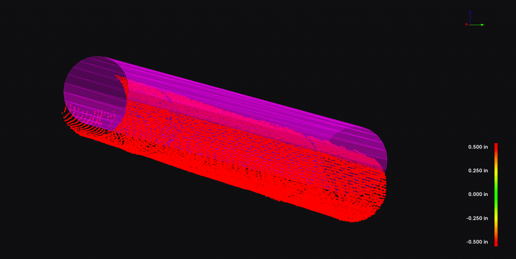
- The AsBuilt heatmap color for each point is a measurement between the point and the surface, normal to the surface. The AsBuilt heatmap colorizes points below (inside) the surface from blue to green. Points above (outside) the surface are colorized from green to red. This colorization provides the best heatmap for evaluating the quality of the fit of the as-built geometry to the point cloud. The heatmap allows you to easily visualize the deformation as well as shape variances between the as-built geometry and the point cloud.
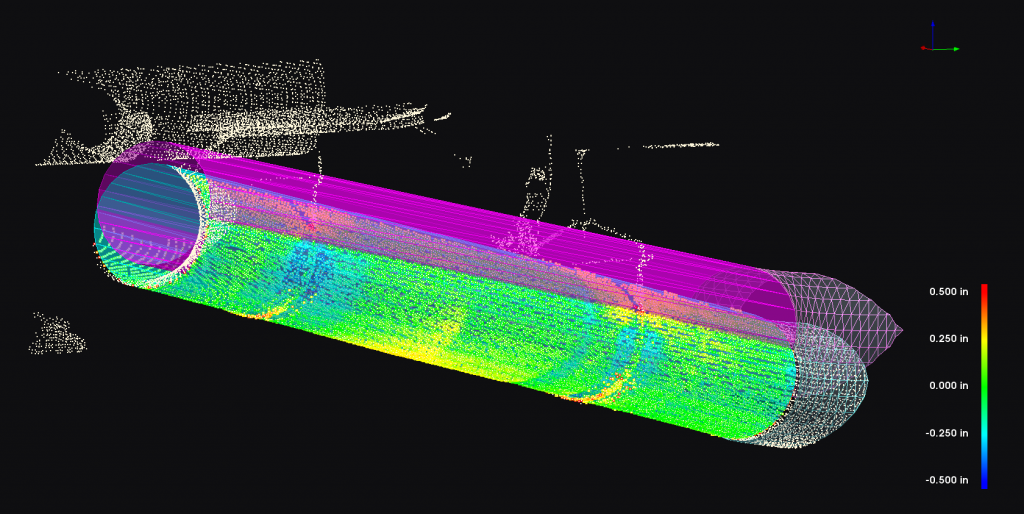
- The AsDesigned heatmap color for each point starts with the AsBuilt heatmap measurement and then adjusts for the distance to the same spot on the As-Designed geometry. This operation allows Verity to colorize points that happen to be adjacent to one part of the as-designed geometry but are distant from the part of the geometry they are associated too. If the As-built object is incorrectly fit this heatmap will not be accurate since it relies upon the As-built geometry as a basis for its calculation. This heatmap only colorizes points from green to red since the relationship to the as-designed surface is corrected, and therefore Verity cannot tell “inside” from “outside.” This heatmap is best to help visualize the rotation and translation of the as-built location relative to the As-Designed geometry. For large displacements, this colorization will effectively be all red.
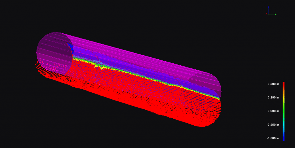
- The AsDesigned Uncorrected heatmap color for each point ignores the As-Built geometry and makes a raw comparison of the point cloud data to the closest point on the As-Designed geometry. The result is a more traditional heatmap you might be used to seeing from other software products. This heatmap does use the As-Built geometry to identify the points to add to the heatmap, so it won’t apply colorization to adjacent points that are not associated to the As-Built object. Because there is no correction, this heatmap does support a full blue-to-red spectrum in the same manner as the As-Built heatmap. This heatmap is best for floor flatness, wall flatness, or other cases where the overall translation of the object isn’t highly relevant to the quality assurance of that type of item.
Verity Heatmap Gradient
You can also change the gradient that is used for the heatmap. There are three options to choose from, and all of these will be correctly reflected in the heatmap scale legend.
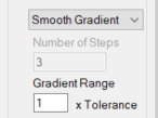
- Smooth Gradient is the default color gradient. The scheme maps the color of the points to a 512-step gradient across the range of the heatmap. Green (0,255,0) is used for the points on the surface of the object. Red (255,0,0) is assigned to points on or beyond the range of the heatmap (dictated by the gradient range setting). In cases where Verity can differentiate between points that are above (or outside) the surface and points that are below (or inside) the surface, points that are below will be mapped between green and blue (0,0,255) instead of red, resulting in a 1024 step gradient. The options to control gradient steps will be greyed out if this option is selected. Above, you can see a floor with a smooth gradient applied to the 0.5-inch gradient range.
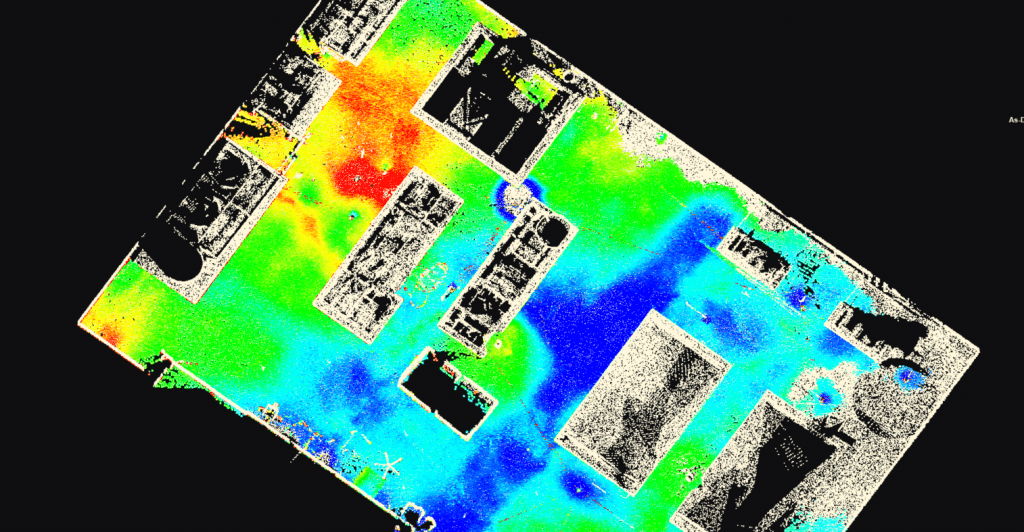
- Stepped Gradient (number) will allow the user to specify the number of steps contained in the gradient range. The user defines a fixed amount of steps that splits the gradient range according to the number. The size of these steps will change per item if the tolerance is set differently through the analysis, but the number of steps will be consistent across items. Above you can see the same floor with the stepped gradient (number) applied to it, with two steps across the 0.5-inch gradient range.
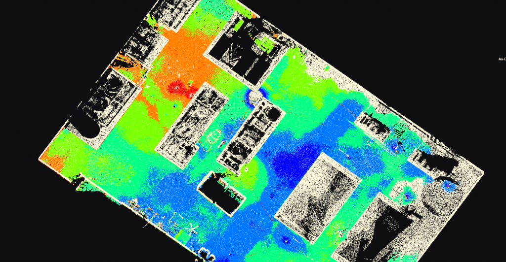
- Stepped Gradient (dimensional) will allow the user to specify the size of the step in the active project units. The user can set a fixed size for the step to divide the gradient range. The number of steps will change per item if the tolerance is different through the analysis, but the size will remain consistent across items. Above, you can see the same floor with a stepped gradient (in) with a step size of 0.5 inches resulting in 4 steps when applied to the 0.5-inch gradient range.
Verity Heatmap Gradient Range
The range over which a heatmap is applied is related to the tolerance of each item. The gradient range is defined as a multiplier of tolerance. So, an item with a gradient range of 1.0 will have a heatmap that spans from green to red across the item’s tolerance. Red (or blue) will be applied to any points that are up to double that distance away from the object. Any points outside that distance will have no color mapped to them and be excluded from the heatmap.
For an item with a tolerance of 25mm or 1 inch:
- Gradient range of 1.0 will result in points within 25 mm or 1 inch being colored with the gradient, points between 25mm and 50mm or 1 to 2 inches being colored red (or blue), and points beyond 50mm or 2 inches being excluded. As such, any out of tolerance points will be red (or blue).
- Gradient range of 2.0 will result in points within 50mm or 2 inches being colored with the gradient, points between 50mm and 100mm or 2 to 4 inches will be red (or blue), and points beyond 100mm or 4 inches will be excluded. As such, points that are out of tolerance will be yellow to red.
The gradient can be adjusted to any number between 0.01 and 9.99. Generally, the most common settings are 1 and 2.
Verity Heatmap Scale
This checkbox toggles on/off the heatmap scale legend that appears in the lower right corner of the Verity Viewer window. These numbers are based on the end and middle of the gradient range, and the colors will be updated based on the heatmap gradient settings.