Search Knowledge Base by Keyword
Getting Started
This article will cover the Verity view controls. To get started, select an element in the Verity item table, and display it in the Verity viewer.
Verity Color Codes
Now that the item has been analyzed, you’ll see several types of geometry in the Verity Viewer window along with the points that fell within the object’s bounding box. The types of geometry are colored as noted below to differentiate which is the original as-designed geometry, which is the best-fit as-built geometry, and which is the analyzed neighboring geometry.
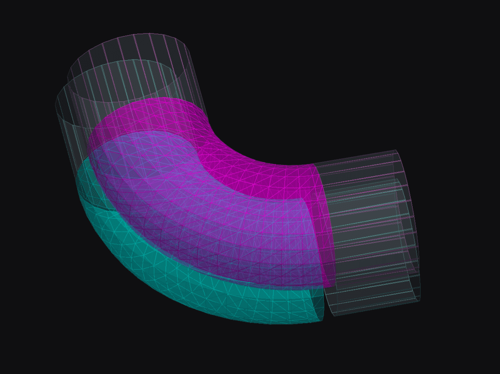
- As-Designed – The as-designed geometry represents the original location in the Navisworks file before Verity analyses it. This geometry displays in a Magenta color.
- As-Built – The As-Built geometry represents where our algorithms best-fit the geometry to the point cloud data.
This geometry displays in a Cyan color. - Neighbor – Any neighboring geometry than Verity has analyzed and is visible within the search box around the selected item. This geometry displays in a Gray color with a Magenta or Cyan wireframe accordingly.
- There is a legend that you can display in the Verity application that graphically shows the four types of geometry and how they are colorized on the screen:
Verity will only display the As-Designed geometry if there is no As-Built position identified (items with the occluded, not found, not enough data, or no data installation status).
Verity Camera and View Frames Controls
These tools help you control the camera in the Verity Console. These will not affect the view settings in the host application UNLESS the Match View Frame tool is active. When active, changing the view frame will update the camera position in the host application as well.
Verity Split View / Single View Controls
Change between the two viewer modes using the Split View button in the View Controls panel. (Button located on the far left)
- Single View – An isometric view of the element oriented to set the camera down the long axis for most elements; you can pan using your middle mouse button (MMB) or use shift+MMB to orbit the view. The single view is the default view on starting Verity.
- Split View – The isometric view moves to the top left corner and orients so that the two adjacent sides of the item with the most point coverage are facing the camera. You can pan and orbit using the same controls above. A projected plan view placed in the upper right (top view). Two corresponding projected elevation views in the lower two panes (the front view is lower right, the side view is lower left). The projected views provide access to additional functionality, such as manually moving the as-built geometry. You can pan the projected views just like the isometric view, but cannot orbit them.
Verity does its best to guess the long axis of the geometry based on its dimensional characteristics. The face that is closest to vertical defines the “Top” of the geometry. The view parallel to the long axis defines the “Front” of the geometry. The view perpendicular to the long axis defines the “Side” of the geometry. In cases where the long axis is near-vertical (columns), Verity chooses the next longest axis to define the “Front” of the geometry.
In cases such as a beam that is deeper than it is long or geometry that is roughly the same length as width, Verity may not choose the correct long axis. The views generated by Verity may be incorrect. Luckily, this is an infrequent occurrence.
View Frames (Coordinate Systems)
We have three view frames that determine the angle at which the camera is looking at the items to help you evaluate the results and compare them back to the host application:

- As-Built – The Zoom As-Built button will align the camera’s frame to the as-built geometry. This is the default setting for views if an As-Built location is found.

- As-Designed – The Zoom As-Designed button will align the camera’s frame to the as-designed geometry. This is the default setting for views if no As-Built location is found.

- Project Coordinates – The Align to Project button will align the camera’s frame to the Autodesk® Navisworks® Project’s coordinate system.
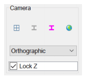
Verity Camera Style Control
The camera style setting configures how the camera views the items and controls how the navigation works. These settings affect the primary isometric view only. Specific projection or other specialized views will be set according to their purpose.
Verity Camera Style Drop-down Control
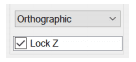
- Orthographic – This is the default option. In Orthographic mode, you will be able to pan the geometry by pressing your middle mouse button and dragging, orbit the geometry by holding shift while pressing your middle mouse button and dragging and change the size of the geometry on the screen by scrolling the mouse wheel.
- Perspective – This mode will change to a perspective projection in the isometric view and behaves similarly to the Orthographic mode, but with the scroll wheel zooming in and out.
- Scanner – This mode will lock the camera position to the location of the scanner with the most coverage on the selected item, with the camera navigation in a “look” mode. Pressing the middle mouse button and dragging will allow you to change the look direction, but not the camera position. Holding down shift while pressing the middle mouse button and dragging will behave the same. The scroll wheel will allow you to zoom in and out on the item.
Lock Z – allows you to toggle between a locked Z-axis and three axes of freedom when orbiting around the object. This is defaulted on.
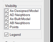
Verity Item Visibility control
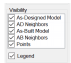
The visibility of all types of geometry, as well as the point cloud, can be toggled on and off using the Visibility controls in the View Control Panel. Also, you can toggle on/off a legend that shows how each type of geometry is displayed.
Verity Item Opacity control
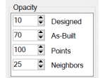
In addition to toggling the visibility of each type of geometry, you can change the opacity of the surface geometry and the points. This is represented as a percentage (0-100) and increases or decreases the opacity for each type of geometry independently. If you want to achieve a wireframe style view for any kind of geometry, you can set the opacity to 0%.
Verity View Point Visualization Control
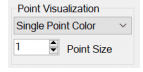
The colorization of the points within the geometry’s bounding box can be controlled using the Point Color drop-down in the View Control Panel. There are three different display options that can be selected. First, the Single Color (chosen by default to stand out on the Verity background). Second, the Colors From Host, which will be either RGB or Intensity values depending on your point cloud. Third, to color the point cloud by Scan Location. The ten scans with the most coverage on the item will be mapped to unique color values, and any remaining scans will remain white. You can also choose the rendering size of the points on the screen, which is particularly helpful on a high-DPI monitor.