Once Verity Photo notes are aligned to a model, it’s possible to perform 3D measurements directly on the image by using the model for reference. For example, let’s say that we want to measure the height of the highlighted light switch box in the photo.
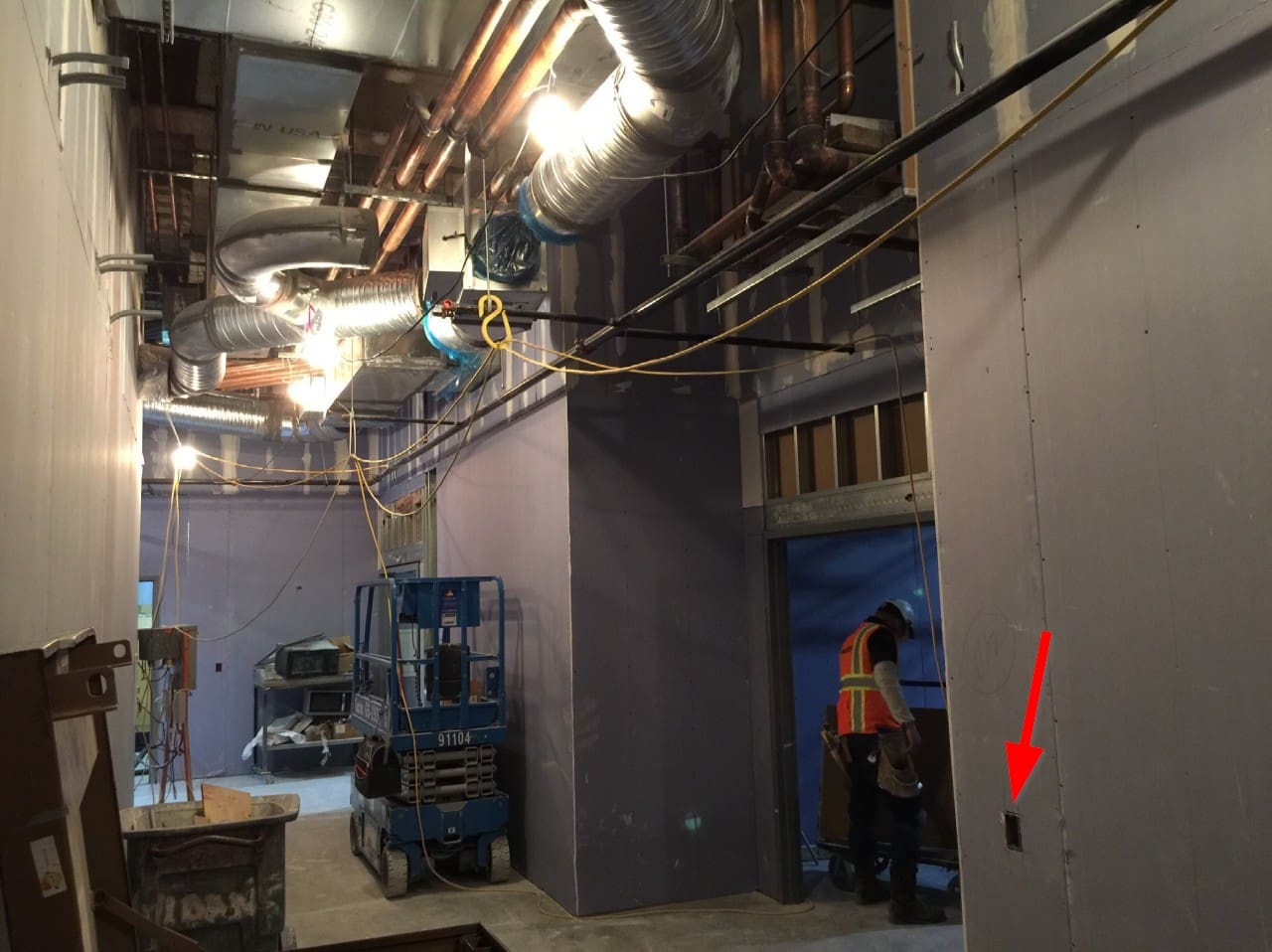
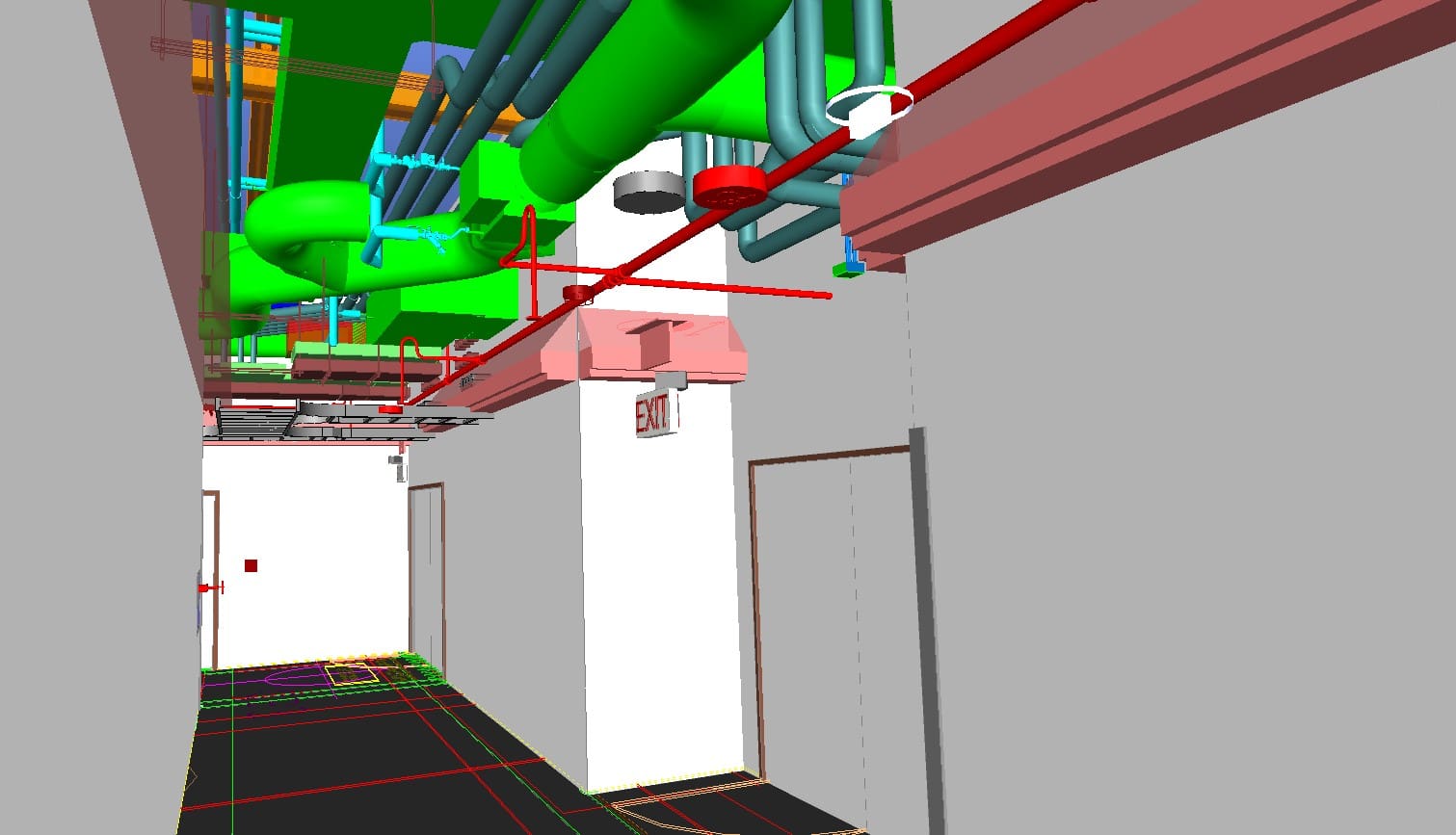
Note the switch box location is not in the Autodesk® Navisworks® model:
First, we start with an aligned note … for now we’ll just use the note we aligned earlier.
In order to perform a measurement-on-image in Verity Photo, we need to place a Measurement Grid in the model that contains the distance line we want to measure.
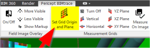
To place the measurement grid, choose Set Grid Origin and Plane from the Verity Photo toolbar
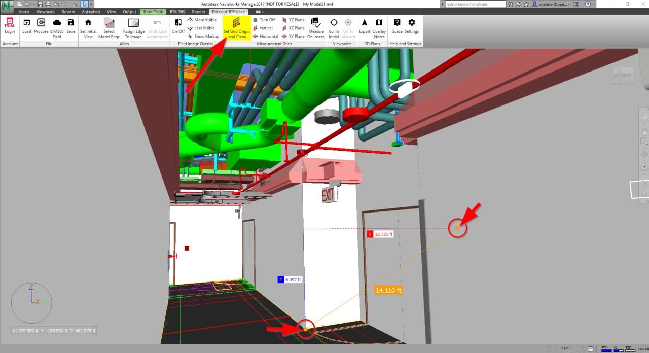
The cursor will change to the familiar Navisworks® line measurement tool. Now measure a line in the plane you want to measure in. In this case since we want to measure a distance on the near wall (from the floor to the outlet), we’ll make sure the line is in the plane of the near wall (anywhere in this plane will work).
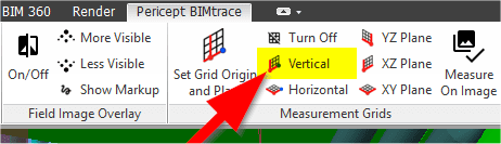
Next we choose the type of grid we want to place. In this case, since we want the grid to be vertical, we’ll choose Vertical
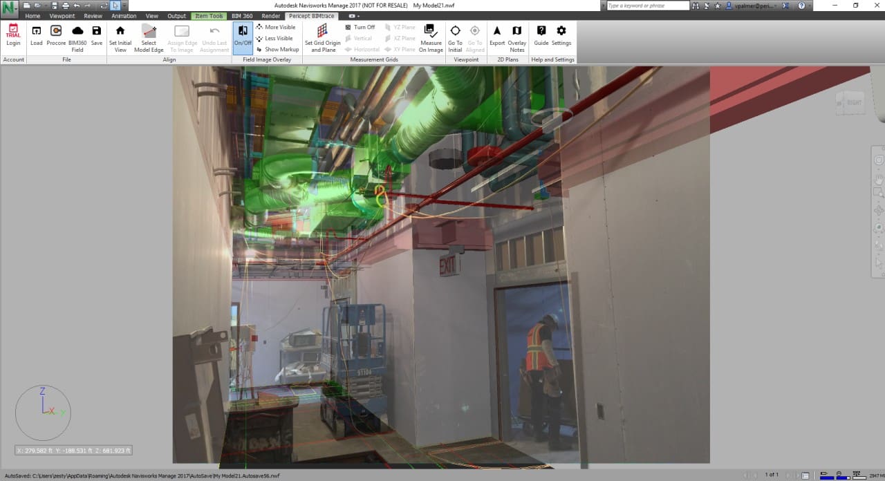
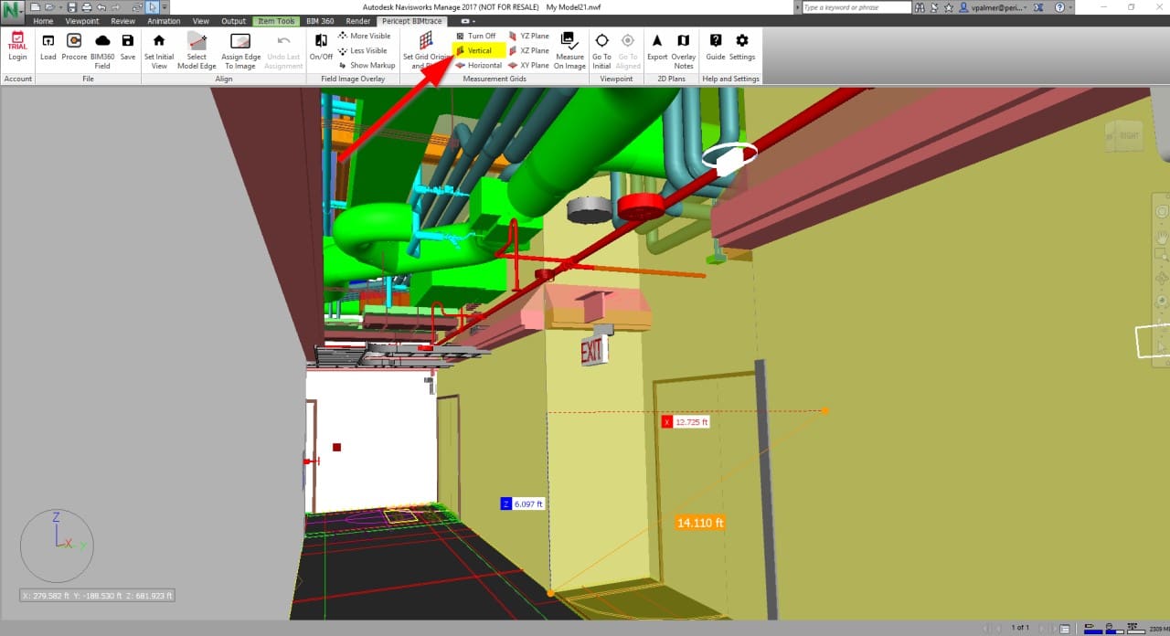
A yellow plane will be merged into the scene at the position and orientation we requested. If this is the first time you’ve used Verity Photo measurement grids in this Navisworks® model, Verity Photo will ask you if it’s okay to merge in additional geometry, so click Yes.
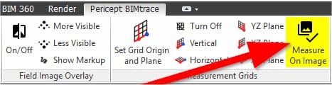
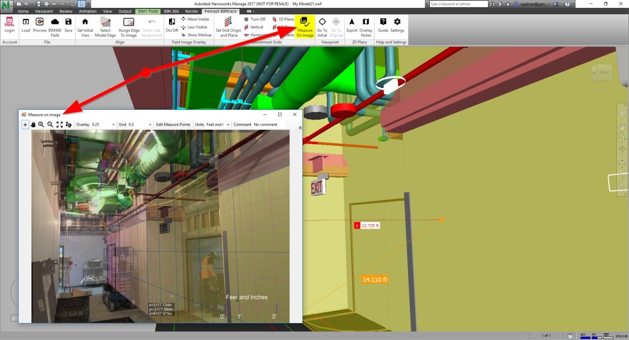
If you are satisfied with the measurement grid placement, click Measure on Image:
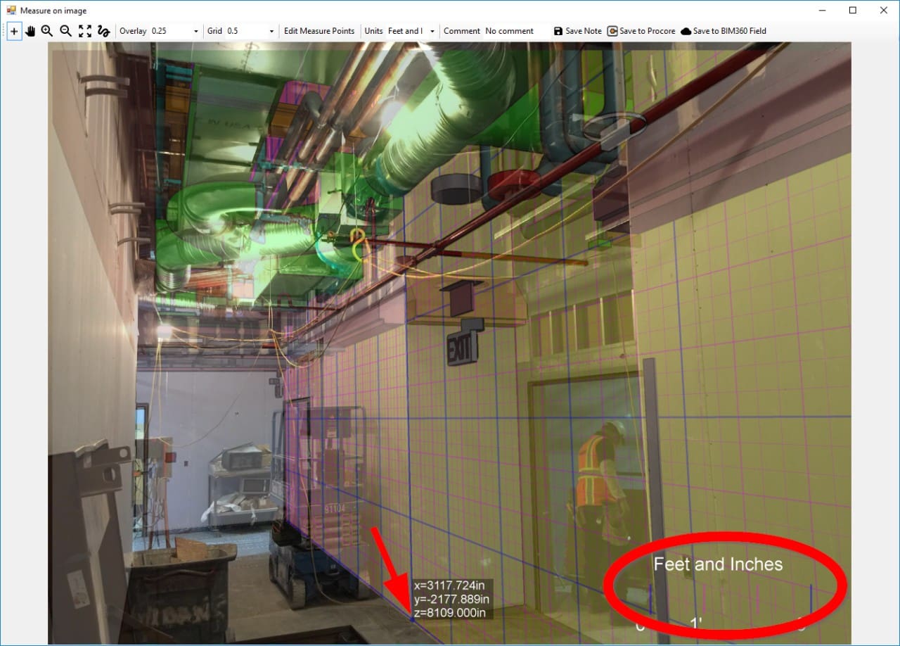
A new measurement window will open with a metered grid rendered on our measurement plane.
The Measure on Image window shows a metered grid (units circled in the image, these units can be changed with the controls at the top of the window). The grid origin is shown as a blue dot (arrow in the image). This origin can be moved by Ctrl+Clicking anywhere on the grid.
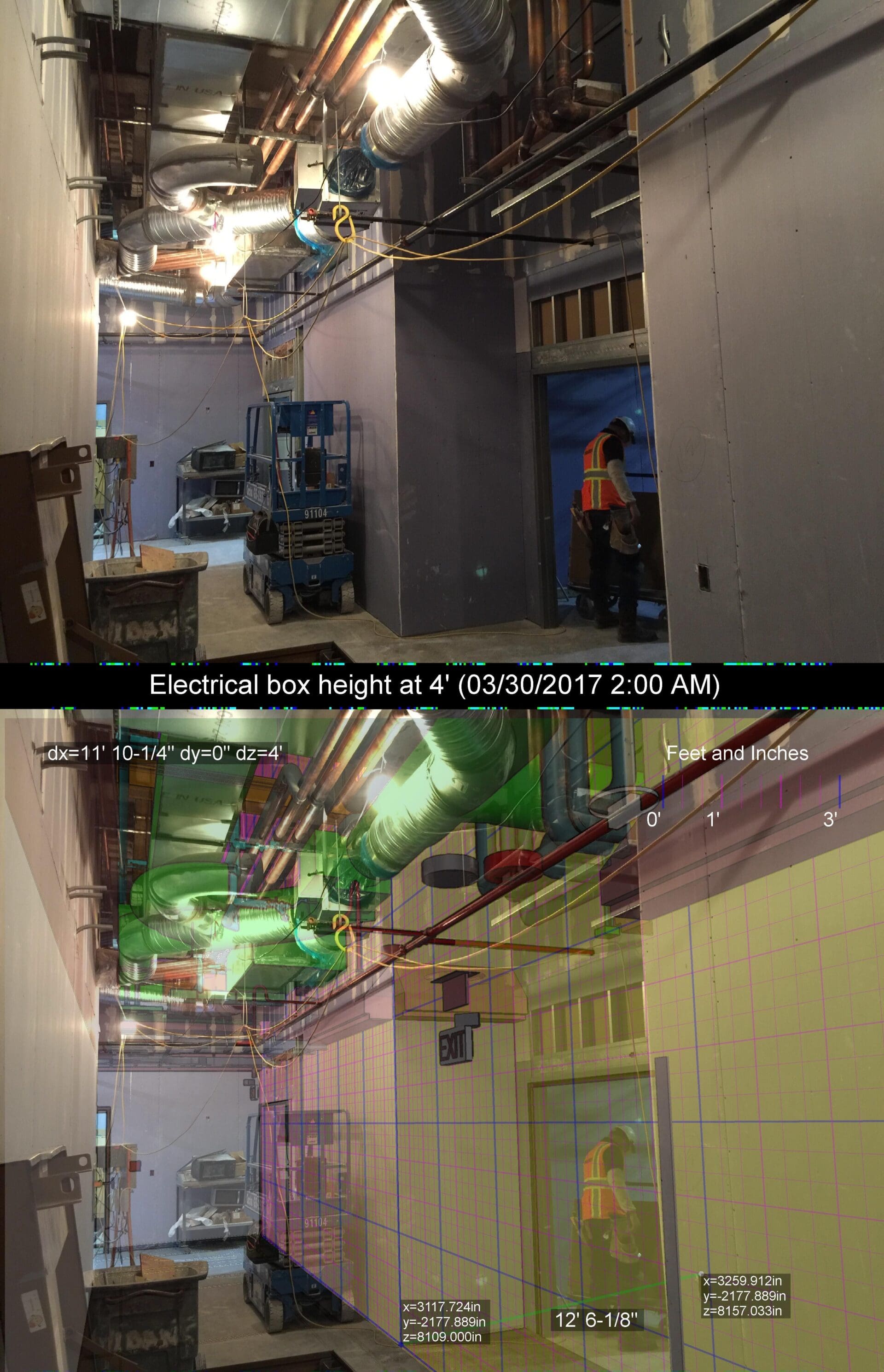
To measure a distance along the grid, simply Left-click anywhere on the yellow measurement grid plane. For example, we can measure from the floor point (the origin is already on the floor) to the top of the light switch box:
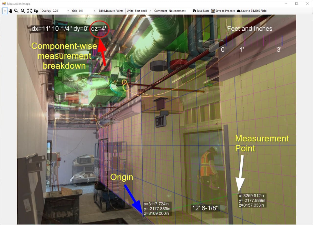
A green line is drawn from the origin (blue dot) and the measurement point (white dot). Here we are only interested in the vertical distance between the floor (origin) and the top of the switch box (measurement point). We can use the component wise-breakdown in the corner of the image which gives the X,Y, and Z components of the distance between the original and measurement point.
Here we see the vertical/dZ distance to be 4′, which is as expected since the switch box was likely installed with its top at 48″ to ensure compliance with the Americans for Disabilities Act required maximum height for light switches.
This composite view, with measurement, can also be saved as a new note for later presentation by selecting Save Note.