
What LOD and LOA Really Measure and Why It Matters
LOD defines what’s in a BIM model. LOA defines how accurately it reflects reality. In Scan-to-BIM workflows, confusing the two can lead to misaligned expectations, rework, and a loss of trust.
Introduction
Few topics create more confusion in Scan-to-BIM workflows than Level of Development (LOD), and Level of Accuracy (LOA). The terms are often used interchangeably, dropped into proposals without explanation, or fully understood only after a project begins to go sideways.
LOD has long served as a shorthand for defining the scope of a model. But as-built modeling introduces a different challenge: accuracy isn’t implied. A model can be visually complete, highly detailed, and convincing at first glance, yet still deviate from real-world conditions in ways that matter. In other words, it may appear correct but still fail to meet its intended purpose.
That distinction becomes critical when models transition from documentation to coordination, fabrication, or construction. Without a shared understanding of how closely a model must reflect reality, teams are left to fill in the gaps themselves, often discovering misalignment only when it’s expensive to fix.
This is where LOA comes in. Rather than describing what’s modeled, LOA focuses on how accurately it represents the physical world. Understanding how LOD and LOA differ and how they work together can help teams establish clearer expectations, minimize rework, and foster trust in model-based workflows from the outset.
What LOD Actually Means (and What It Doesn’t)
Featuring Insights from Kelly Cone – Chief Strategy Officer @ ClearEdge3D
One reason LOD continues to cause confusion is that it is often used to describe two related but fundamentally different concepts.
In casual usage, LOD is often interpreted as Level of Detail, referring to how much geometry, annotation, or visual complexity is present in a model element. However, as clarified in the BIM Forum LOD Specification (2025), LOD is formally defined as Level of Development, a measure of how much reliance can be placed on a model element for a specific purpose.
Level of Detail describes how much is shown.
Level of Development describes how far along an element is and what it is suitable for.
These ideas are connected, but not interchangeable. The BIM Forum explicitly notes that a model element’s appearance alone can be misleading, particularly in digital environments where schematic and construction-ready content may look nearly identical. Sharing a single acronym for both concepts has only amplified that ambiguity.
Kelly Cone: In the days of hand drafting, the medium itself, trace paper versus vellum versus Mylar, told you a lot about how far along a design really was.
CAD and BIM technology turned that on its head. You place a door during conceptual design, and it already contains every detail, even though it might get moved tomorrow.
Level of Development was intended to define, through specification, what used to be implicit in the medium.
BIM Levels of Development (LOD 100–400): From Conceptual Representation to Construction-Ready Models
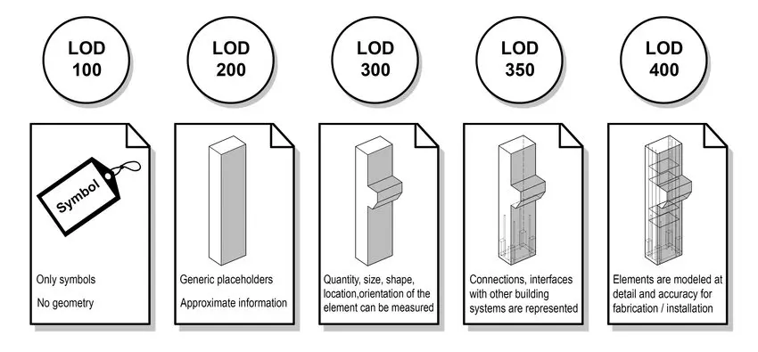
Example of BIM Levels of Development (LOD 100–400), showing how model elements evolve from symbolic placeholders to more detailed, construction-ready geometry as a project progresses. Adapted from BIM Forum.
What LOD Is Meant to Communicate
In traditional design workflows, early concepts were intentionally loose, while construction drawings became more refined as decisions were validated. The visual fidelity of a drawing reflected the maturity of the design behind it.
That signal largely disappears in modern BIM tools.
KC: The problem with modern BIM tools is that a schematic model and a construction-ready model can look almost identical. The software makes things appear more complete than they actually are.
The BIM Forum LOD framework exists to reintroduce that lost signal. LOD levels (100–500) are intended to communicate design intent, completeness, and permitted use, not whether geometry has been verified against physical reality.
Because design content is often reused across phases, and sometimes across projects, models can carry high visual and informational detail long before key decisions are finalized. Level of Development exists to clarify what assumptions are safe to make about an element at a given stage.
KC: LOD is there to specify what owners require from their designers to enable their contractors to price and build the project. It doesn’t address how accurately something has been modeled compared to what has already been built.
In other words, LOD defines what a model is fit for, not how correct it is.
Why LOD Became the Default Standard
Despite these limitations, LOD became the default way to describe as-built and existing-conditions models largely because it was already familiar and widely adopted.
KC: LOD became the default standard for as-built modeling simply because it was the default standard for everything else. People understood it, so they applied it, even when it wasn’t really suited for the task.
This is where friction emerges. As-built modeling works in reverse: teams begin with something already built—often irregular, partially undocumented, and shaped by field conditions—and attempt to describe it using a framework designed around design progression.
KC: With existing conditions, you’re swimming upstream. You’re taking something that’s already built and partially unknown and trying to force it into a specification that was designed for design documentation, not reality.
The BIM Forum LOD Specification acknowledges this limitation by treating LOD as a statement of model use and reliability, not a declaration of geometric truth.
What LOA Measures and Why It Exists
Featuring Insights from Brendan Flavin – BIM & VDC Expert
While LOD has become a familiar way to describe how detailed or developed a model is, it doesn’t answer a more fundamental question for existing conditions work: How closely does this model reflect reality? That gap is exactly why Level of Accuracy (LOA) exists.
As Brendan Flavin explains, LOA is focused on a very specific, and often misunderstood, dimension of model quality:
Brendan Flavin: When employing laser scanning, Level of Accuracy measures how closely a BIM model reflects the real-world conditions captured in the point cloud. In practice, it focuses purely on geometric accuracy, including the position, size, and shape of modeled elements from the point cloud data.
How USIBD Levels of Accuracy Translate into Real-World Tolerances
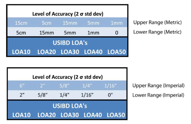
USIBD Level of Accuracy (LOA) tolerance ranges (LOA10–LOA50) shown in metric and imperial units, highlighting the distinction between measured data accuracy and represented model accuracy.
What LOA Measures in Practice
Unlike LOD, which describes how much information or detail a model element contains, LOA is concerned solely with geometric reliability. Two models can meet the same LOD requirement and still differ significantly in how accurately they represent the physical site.
BF: Defining LOA separately is necessary because two models can have the same LOD yet vary significantly in accuracy. By introducing LOA, project teams can clearly communicate how precise the geometry needs to be.
In real-world Scan-to-BIM workflows, this distinction matters. A model intended for coordination, renovation planning, or construction decision-making must be accurate enough to support those uses, regardless of how visually complete it appears.
Why LOA Is Especially Important for As-Built Modeling
Accuracy takes on heightened importance when working with existing buildings. Unlike new construction, existing facilities often include undocumented changes, field deviations, and accumulated tolerances that aren’t reflected in legacy drawings or models.
BF: LOA is critical in existing conditions and scan-to-BIM workflows because these models are used as the foundation for design, coordination, and construction decisions. Clearly defined accuracy, a model could misrepresent these conditions, leading to costly mistakes or rework down the road.
In practice, Flavin notes that many Scan-to-BIM projects are delivered at LOA 30, which provides a reliable level of geometric accuracy for renovation design and coordination. Projects involving prefabrication or tighter tolerances may require LOA 40 to ensure higher precision. The key is that the required accuracy is defined up front, rather than assumed.
Understanding the Gap Between Measured Data Accuracy and Modeled Surface Accuracy
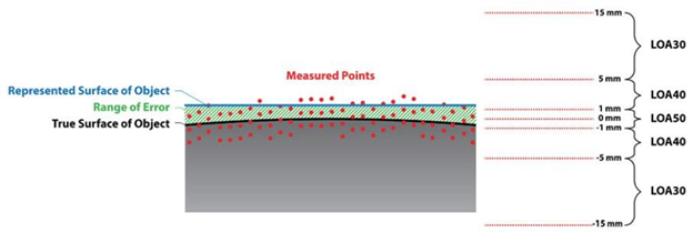
Relationship between measured point cloud accuracy and represented surface accuracy under the USIBD Level of Accuracy (LOA) framework.
How LOA Complements, But Does Not Replace, LOD
A common misconception is that specifying LOD alone is enough to ensure a model can be trusted. In reality, LOD and LOA answer different questions, and both are needed.
BF: Many teams initially assume that if a model meets a certain LOD, it must also be accurate, but LOD and LOA measure different things.
He summarizes the relationship simply:
BF: LOD tells you what’s in the model and how complete it is; LOA tells you how correct it is.
In practice, this distinction becomes clearer when the two are paired. For many Scan-to-BIM renovation and retrofit projects, deliverables commonly fall around LOD 350 with LOA 30. At this level, elements are modeled with sufficient detail and coordination for design development and clash detection, while geometry is typically expected to fall within roughly ¼″–½″ of real-world conditions, depending on element type and validation method.
Together, LOD and LOA provide a more complete definition of model expectations. LOD ensures the model contains the right level of detail for its intended use, while LOA defines how closely that detail aligns with physical reality. Relying on one without the other leaves room for misunderstanding and risk.
Why Scan-to-BIM Projects Break Without LOA
Featuring Insights from John M. Russo – Founder of the U.S. Institute of Building Documentation (USIBD) & President/CEO at Architectural Resource Consultants (ARC)
Scan-to-BIM projects rarely break because teams didn’t model enough detail. More often, they break because accuracy was assumed rather than clearly defined, validated, and carried through the workflow from capture to modeling to downstream use.
The Role of Scan Quality and Registration
Accuracy issues almost always originate earlier than teams expect, well before modeling begins. Scan quality, field procedures, and registration methodology establish the upper limit of how reliable a model can ever be. When data is collected without a clear understanding of the intended deliverable, or when registration is performed without rigorous validation, errors can compound.
Field execution is not a neutral step in the Scan-to-BIM process. Decisions made during scanning—overlap, control strategy, resolution, coverage, and validation—directly determine whether the resulting point cloud can support the specified accuracy requirements. Poor scan quality limits registration quality, and weak registration quietly creates errors throughout the dataset long before a modeler ever begins their work.
As John Russo, Founder of the U.S. Institute of Building Documentation (USIBD) and President/CEO of Architectural Resource Consultants, explains:
John Russo: Accuracy begins with the very first scan, and with the technician understanding the intent of the deliverable. The role of the technician is not simply to collect data, but to collect purpose-driven data using best-practice field procedures that minimize error from the outset.
Scan quality directly impacts registration quality, and poor registration compounds errors long before modeling begins. Taking the time to properly clean and validate scan data significantly improves registration results and overall dataset reliability.
Since modeling inherently introduces additional deviation, it’s critical that the point cloud be high quality and verified against the specified Measured Level of Accuracy. Without that foundation, even the most skilled modeling effort cannot produce a trustworthy result.
In other words, modeling is not a corrective step; it is a downstream consumer of data quality. It can structure and interpret reality capture data, but it cannot overcome unclear intent, weak field practices, or unverified registration. When accuracy expectations are not enforced at the point cloud level, every subsequent deliverable inherits that risk—often invisibly, until it becomes costly to correct.
Modeling Decisions That Affect Accuracy
Even with high-quality scan data, modeling decisions play a significant role in whether accuracy is preserved or degraded. Choices around snapping, averaging, simplification, and interpretation all introduce small deviations. Without a defined LOA guiding those decisions, different modelers, or even the same modeler at different times, may make assumptions that quietly push geometry outside acceptable tolerances.
This is where accuracy stops being a technical concept and becomes a process problem. If teams aren’t aligned on how accuracy is being maintained and checked during modeling, inconsistencies are almost inevitable.
Element-Level QA/QC Verification Against Point Cloud Data in EdgeWise
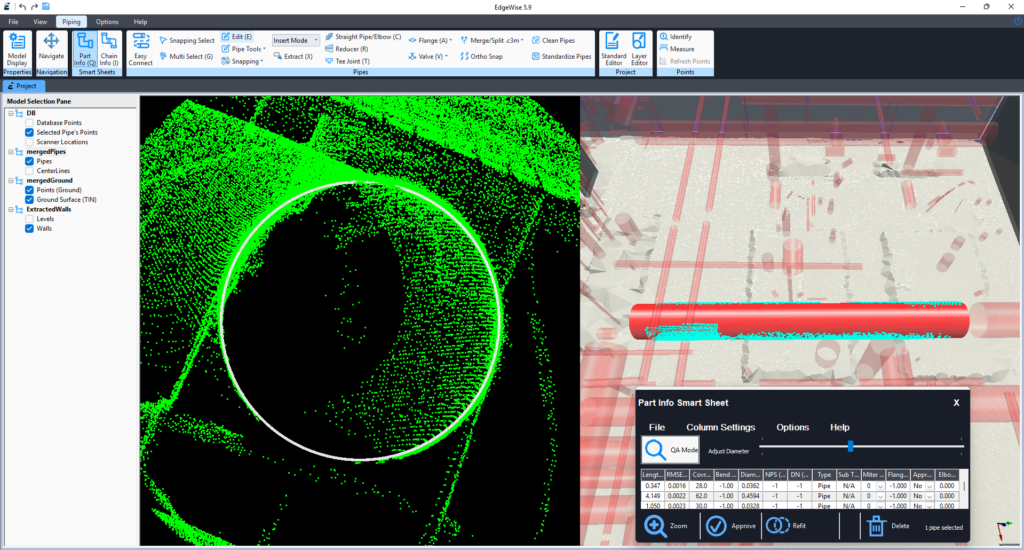
EdgeWise‘s Smartsheet provides element-level QA/QC visibility, allowing teams to visually and analytically verify modeled geometry against point cloud data before downstream use.
Why High LOD Can Still Produce Misleading Results
One of the most persistent misconceptions in Scan-to-BIM workflows is that higher LOD equals higher reliability. In practice, the opposite can be true.
JR: A high level of detail does not equate to high accuracy. If the underlying scan data is inaccurate, increasing the level of detail in the model simply adds more geometry to an unreliable foundation.
In those cases, the model may appear more sophisticated, but it is only providing greater detail of incorrect information. Without validating the measured accuracy of the data, higher LOD can amplify misunderstandings and give stakeholders a false sense of confidence in the results.
Highly detailed models can be hazardous when accuracy hasn’t been validated, because they look authoritative. Stakeholders trust what appears precise, even when it isn’t.
Real-World Impacts: Clashes, Rework, and Loss of Trust
When accuracy isn’t clearly defined and verified, the consequences show up downstream, often when changes are most complex to absorb. Models that appear compliant can fail during coordination, clash detection, or construction, leading to rework, disputes, and schedule impacts.
JR: One of the most common failure points I’ve seen is when an LOA is specified without a clearly defined method of validation. On one project, we were working under an early version of the LOA specification where validation procedures had not yet been formalized.
The project required an LOA 40 model—already a high bar—but the client validated accuracy by taking a single Disto measurement across a room, from one wall to another.
While our modeled wall was within tolerance relative to the point cloud, that cross-room measurement compounded errors from multiple surfaces and falsely suggested non-compliance.
The result was an unnecessary dispute and rework. That experience directly informed later updates to the LOA specification, reinforcing that accuracy is meaningless without a clearly defined and agreed-upon method of validation.
Left unaddressed, scenarios like this can undermine confidence in model-based workflows. Teams stop trusting the data, and the value of Scan-to-BIM is called into question—not because the approach is flawed, but because expectations were never aligned.

Reference the Official LOA Standard
For teams that need level-by-level definitions or formal specification language, the U.S. Institute of Building Documentation (USIBD) provides the authoritative LOA standards and reference materials.
Accuracy Is a Chain, Not a Number
For scanning and modeling teams, accuracy is rarely lost in one dramatic moment. It erodes in small, understandable steps.
A helpful analogy is curtain walls. On paper, a ±1-inch tolerance sounds generous. In reality, that inch is the result of many smaller tolerances stacking together—survey control, concrete placement, embeds, anchors, fabrication, and installation. No single step is wildly off, but the accumulation matters. By the time the curtain wall goes in, installers are often averaging deviations just to make everything fit.
KC: You can’t deliver something more accurate than the weakest link in the chain—and once you account for stacked inaccuracies, you usually can’t even deliver something as accurate as that weakest link.
Scan-to-BIM workflows follow the same pattern.
Scan quality, control setup, registration strategy, modeling assumptions, and validation methods all contribute to the final result. Each step introduces uncertainty. Modeling software prefers straight, square, and plumb geometry, even when the real world isn’t.
This is where scanning and modeling teams often feel the tension. The model looks clean. The geometry is complete. But once it’s used downstream, questions arise about trust, tolerance, and intent. That disconnect isn’t a failure of skill; it’s the result of expectations that were never made explicit.
That’s the real value of LOA. It doesn’t promise perfection. It acknowledges reality. It provides teams with a shared language to define what accuracy means, how it’s measured, and where its limits lie, preventing assumptions from turning into disputes.
The most successful Scan-to-BIM projects don’t start with tighter tolerances or better tools. They begin with alignment: understanding what the model needs to support and accepting that accuracy is always the product of a system—not a single scan, model, or number.
About the Contributors

Kelly Cone
Chief Strategy Officer @ ClearEdge3D
Passionate about process and technology innovation in the AECO industry, Kelly Cone brings a background in architectural design and a career spanning design, estimating, construction, and VDC leadership.
With experience on landmark projects and leading high-performing innovation teams, they now apply that perspective at ClearEdge3D to advance reality capture, computer vision, and positioning technologies that improve how the built environment is designed and delivered.

Brendan Flavin
BIM/VDC Expert
A BIM and VDC leader with more than eight years of experience, Brendan Flavin specializes in digital construction, reality capture, and BIM-to-Field workflows on large commercial projects.
With a background spanning BIM, surveying, and GIS, they focus on enabling effective coordination, construction execution, and asset handover across distributed teams and remote delivery models.

John M. Russo
Founder of the U.S. Institute of Building Documentation (USIBD) & President/CEO at Architectural Resource Consultants (ARC)
John Russo is the President and CEO of Architectural Resource Consultants (ARC), where he specializes in existing-conditions documentation and Digital Twin development using laser scanning and BIM.
A recognized industry leader, he pioneered the Base Asset Model (BAM™) methodology and played a key role in establishing widely adopted standards, including the USIBD Level of Accuracy (LOA) Specification and contributions to the BIM Forum LOD Specification. Russo’s experience spans major landmark projects and federal programs, and he continues to advance best practices in building documentation and spatial data management.