Search Knowledge Base by Keyword
Getting Started
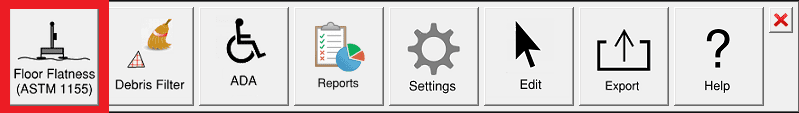
This article will cover how to use the Floor Flatness tool within the Inspector Toolbar. The Floor Flatness tool allows you to create ASTM 1155 Floor Flatness/Floor Levelness runs and reports. To adjust settings for this function, refer to this article.
Create a Debris Filter
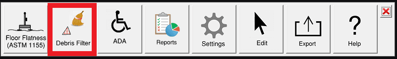
The Debris Filter is used to subsample the points and remove transient noise from the point cloud before applying an ASTM 1155 analysis. See this article to see a full description of the Debris filter tool.
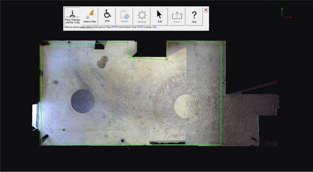
Define You Area
Selecting the Floor Flatness (ASTM 1155) button will require that a surface is defined to limit the effect of the command. When selecting the surface, use the left mouse button to pick points that define the boundary of the surface. Then, press Enter when finished.
Creating Runs
A window with guidance on the ASTM workflow appears after defining an area.
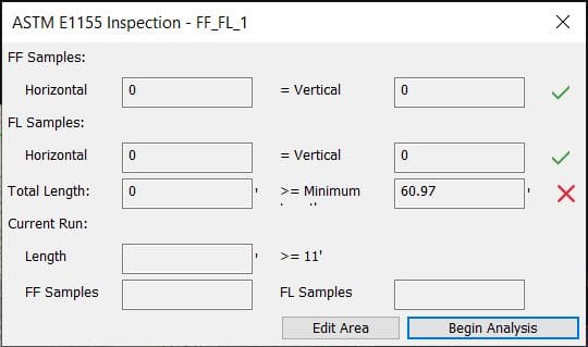
- FF – The number of horizontal and vertical floor flatness samples generated by the drawn profiles. The number of floor flatness samples per profile equals to its length in feet. The number of horizontal and vertical samples should equal each other. A green checkbox appears when this condition is met.
- FL – The number of horizontal and vertical floor levelness samples generated by the drawn profiles. The number of floor levelness samples per profile equals to its length in feet minus 9. The number of horizontal and vertical samples should equal each other. A green checkbox appears when this condition is met.
- Total – The total length of all drawn profiles. The total length of the profiles should exceed the indicated threshold calculated from the surface’s area. A green checkbox appears when this condition is met.
- Current – The length of the active profile line and the corresponding number of floor flatness and levelness samples. Each line must be at least 11’ long. A green checkbox appears when this condition is met.
In order to stay within ASTM compliance, the horizontal samples must to be equal to the vertical samples (this will be indicated by green checkmarks or red X’s in the window).
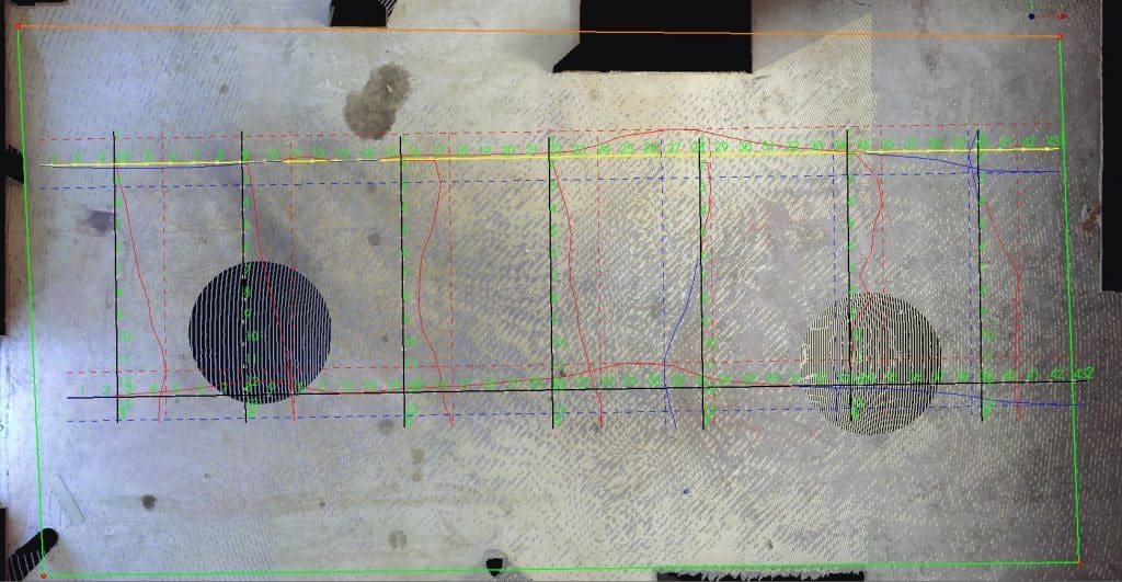
Drawing Lines
After defining an area, left click two points to define the FF / FL run. You can also specify the length of a FF line by pressing a number on your keyboard after identifying your first point in the direction of your cursor.
After you place the first line, use the shift key and left click to place a parallel run line identical to the first. Additionally, you can hold Ctrl and left click to place a run identical in length, but perpendicular to the first.
After you finish creating your lines, click Begin Analysis in the ASTM window to run the FF / FL report.
Reports
After the analysis has been run, a report will appear. On the left side of the report you will see numbers with the associated FF / FL values. On the right side, it shows the elevation values for each step.
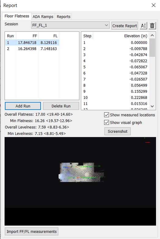
- Add Run: Allows you to add an additional run to the session.
- Delete Run: Allows you to delete the currently selected run in the left hand chart.
- Session Name Dropdown: Allows you to swap between different FF/FL sessions.
- Edit Session Name(Cursor Symbol Button): Allows you to rename the FF/FL session for your report.
- Delete Session(Trashcan button): Allows you to delete the current session in the Session Dropdown.
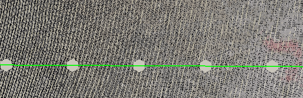
- Show Measured Locations: Keeping Show Measured Locations checked will make each numbered step in the run visible.
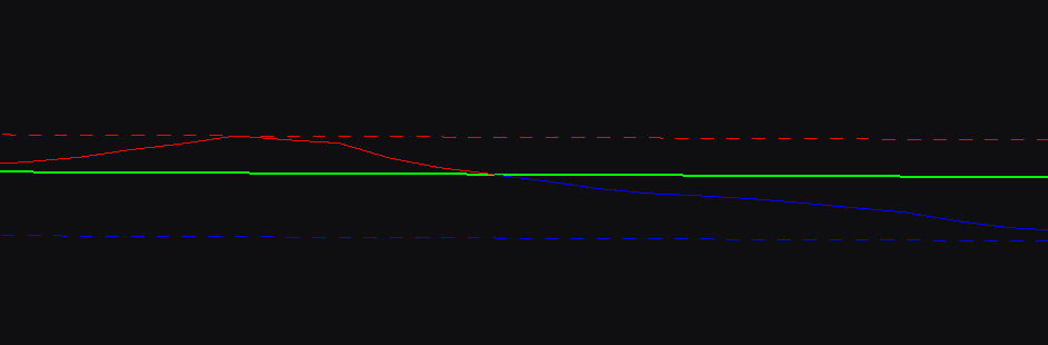
- Show Visual Graph: Keeping Show Visual Graph checked will show the dotted blue line (lowest elevation value), dotted red line (highest elevation value), and a solid blue/red line that exists between those elevations. This solid line shows the elevation value over that distance.
- Run: The order of FF/FL runs.
- FF: Values that depict the Floor Flatness, or how wavy or bumpy a floor is.
- FL: Values that provide information about the Floor Levelness. Levelness is how closely the finished floor matches the intended slope.
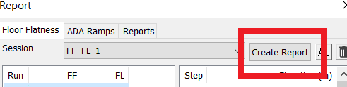
- Create Report: This allows you to produce an FF / FL pdf report. Here you can enter project specific information you want to include in the report.
- Screenshot: Allows you to take a new screenshot that is seen at the bottom of the report dialog. This will also carry over into your final PDF report.
- Import FF/FL Measurements: Allows you to import previously exported FF/FL Measurements.
Reports and Create Report
The Report tab allows a users to set-up the FF / FL pdf report. Here you can enter project specific information you want to include in the report.
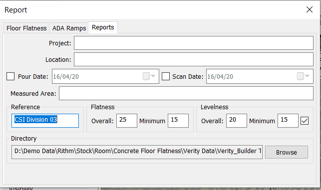
Following the options, the Create Report button in the Floor Flatness tab will create the PDF report. If you would like to edit the screenshot that is produced in the report, simply change your view in the 3d view of Rithm (panning or zooming in or out) and then press the screenshot button in the Floor Flatness Report dialog.
Export
If you would like to export out your floor flatness lines you can do so by selecting the Export button in the inspector toolbar. You can export these lines out as a .dxf file, or Floor Flatness lines. Floor flatness lines are a copy of the lines you produced in your original analysis which can be imported into another Rithm Project using the “Import FF/FL measurements” button at the bottom of the reports page.
Import FF/FL Measurements
To import FF/FL Measurements onto a pointcloud model, first open up the Inspector Toolbar. Once open, select the reports button and make sure the floor flatness tab is selected. Then click the Import FF/FL Measurements button. Browse and select the lines you exported previously, and then click yes.
