Search Knowledge Base by Keyword
Getting Started
The Ducting module inside of EdgeWise allows you to extract rectangular ducting from the point database. This article cover the Semi-Automated Extraction and QA portions of the ducting workflow.
The Ducting module does NOT include an automated extraction process, however, the beginning of the workflow still relies on semi-automated extraction and QA. To begin this workflow, ensure you have a point database model for your project already created and opened.
Click the Blank Model button located under the File tab, then select New Ducting Model. Notice a new model appears in your Model Selection Pane. Select this new ducting model in the Model Selection Pane, then select the Ducting tab in the ribbon.
The Ducting Tab
The Ducting tab includes all of the EdgeWise tools necessary for rectangular ducting extraction and modification. On the left you will see standards, size information, and the extraction tool. The center and right side consist of QA, positioning, and elbow insertion tools.

The first section of the Ducting tab contains two drop down menu boxes. Use these boxes to change the standard and size of the rectangular element you would like to extract. The size can also be left as Autofit. You can import your own custom standards by using the Export Standard button. Refer to the custom standards article for more information.
Semi-Automated Extraction
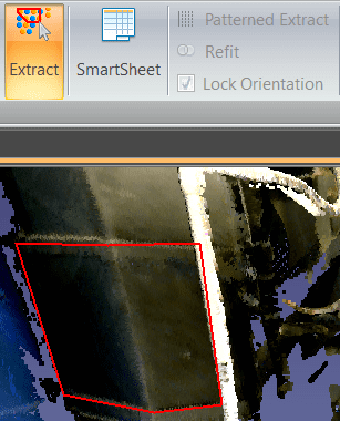
Once your standard and size have been chosen, you can proceed to extract an element. If you would like EdgeWise to find the size for you, leave the size on Autofit. Select your Extract tool from the ribbon, or press the X key on your keyboard. Now, left click to start your selection box, and continue left clicking around your object. When your polygon surrounds your item, double left click to finish the selection. EdgeWise will proceed to find the best fit for your structural element and extract it. Keep in mind, for rectangular ducting you only need to extract out the straight portions of the duct. Elbow and transition insertion will be done automatically later.
If you need to extract more elements of the same size, select your original item, then press the Set to Selected button in the ribbon and EdgeWise will change the size in the catalog to your current selection. Now, EdgeWise will only attempt to extract this item at this catalog size from the point database.
QA Tools
To QA an element, select it in the 3D view, then click the SmartSheet button. Alternatively, you can press your Q key on your keyboard. You should now see two additional windows. First, a 2D view of your selected object and it’s associated point data. Second, a spreadsheet of all the objects in your current project. Additionally, your 3D project will also still be view-able while in this mode.
Left-click and drag the white outlined object in the 2D view to adjust its position in 3D space. Hold shift, then left-click and drag to adjust the tilt of the object. Use the rotate buttons on the far right side of the ribbon to rotate the object 90 degrees left, right, or flat.
Additional QA Tools
- Press the Refit button and EdgeWise will attempt to refit the object back to the point data.
- Use the Thicker and Thinner buttons in the ribbon or the Size drop-down in the Smartsheet to change the catalog size of the selected object.
- Select Resize, then left-click and drag a box around the green point database data and EdgeWise will find the closest size based on your selection.
- The Mirror tool will swap the start and end points of a selected linear object .
- The Snapping tools allow you to snap selected objects to various settings like parallel, vertical, or collinear.
- Copy Size can be utilized when you want selected objects to be the same size as another object. Select the items whose size you wish to change, click Copy Size, then select the object with the desired size.
- Extend allows you to extend your selected item or items to another geometrical surface’s plane.
Modification in the 3D View
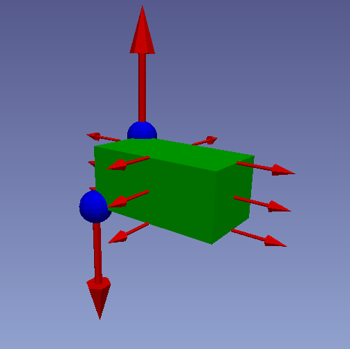
While your object is selected in the 3D View, you have additional options for translation and modification. Use the small red arrows in the center of your object to move the element along a plane. Use the small red arrows on the edges of your duct to rotate the element. The large red arrows on either end are used to increase or decrease the length of the element. The blue ball on either end can be used to free-form tilt the object. You can also click and drag the element in 3D space from any view point.