Search Knowledge Base by Keyword
Getting Started
This article will cover general information regarding the Structured Process Scans workflow. Process Scans is the first step in any EdgeWise Project, and consists of three different workflows: Structured, Unstructured, and Point Database Process Scans.
The structured workflow can automatically extract piping, walls, and ground models. The scan files need to be registered, and structured/ununified (containing row and column information) to use this workflow.
File Types
The specific structured file types that can be brought into EdgeWise are listed below:
- Trimble .TZF
- Leica .PTG
- Z+F .ZFS, .ZFPRJ
- DotProduct .DP
- Gexcel .RGP
- .E57 (Structured)
- .PTX
- Recap .RCP (Structured/not unified)
- Note: When processing a point cloud in structured .RCP format, EdgeWise will read through the RCP Support files to ensure all necessary point information is present. This process will cause a small delay before the Process Scans Options dialog opens; please allow a few moments for the pre-read to complete.
Process Scans
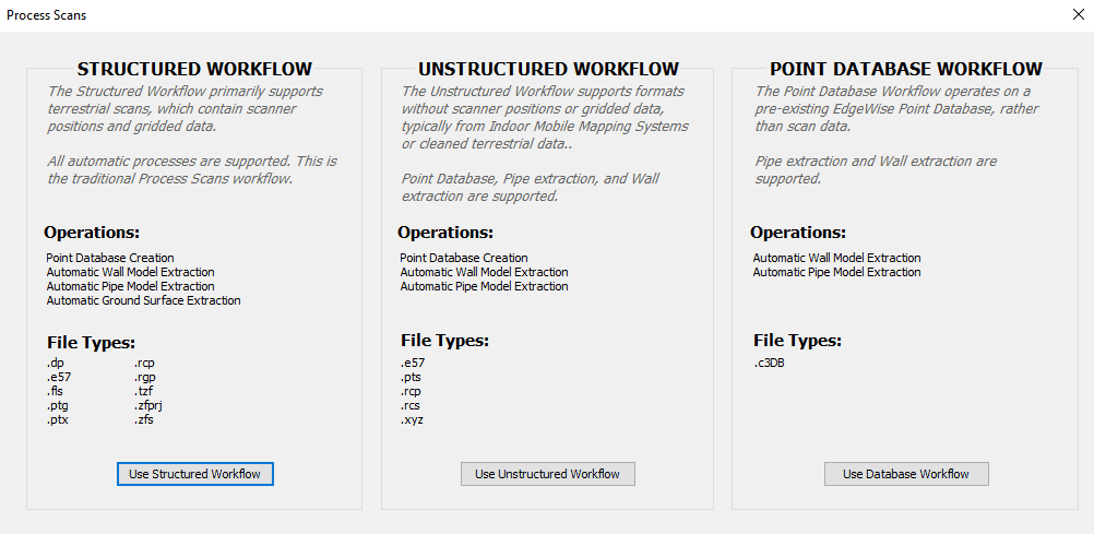
To process your scans, first click the Process Scans button located under the file tab. Upon clicking the Process Scans button, the Process Scans dialogue box will appear. If you have Structured data, use the Structured Workflow. First, start by clicking the Use Structured Workflow button.
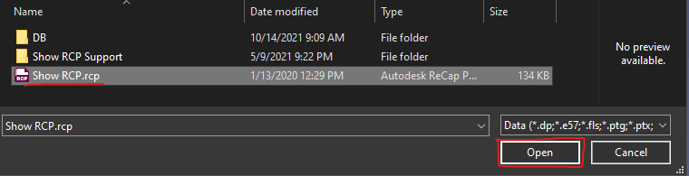
After you click the Use Structured Workflow button, a File Explorer will appear. Navigate to the location of your scan file(s), select all of your scan file(s), and click the Open button.
After clicking the Open button within the File Explorer, the Process Scans Options dialogue box will appear.
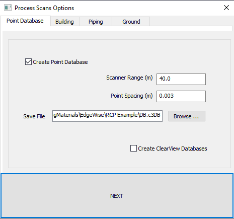
The Process Scans Options dialogue box allows you to choose which modules will be automatically processed in addition to changing the respective modules’ processing settings. The various sections below, cover each module’s settings in detail.
Point Database
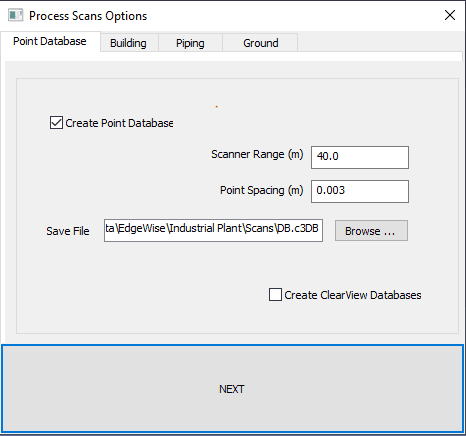
Before EdgeWise can display a point cloud, you must first convert your scans to a .c3db point database model.
Scanner Range – EdgeWise uses this parameter to determine how far away from the scanner location points can be included in the database.
Point spacing – the minimum spacing between points saved in the database. The larger the number, the sparser the point cloud will be. Denser point clouds may look slightly better, but they take considerably more disk space and time to create.
Create ClearView Databases – is an option to create a point database used for viewing the project using the ClearView setting—see ClearView Mode. Note: Creating this additional database can potentially increase processing time for certain scans upwards of two- or three-fold.
Building
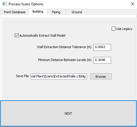
EdgeWise will automatically extract walls and levels in this automated process. In addition, support is available for this process for the Structured, Unstructured and Database workflows, and supports all available file types. Check Automatically Extract Wall Model and EdgeWise will automatically create a wall model during process scans. If you do not wish to extract walls, simply un-check the box.
Wall Extraction Distance Tolerance – When EdgeWise is attempting to automatically detect a wall, this tolerance controls the maximum distance a point can be from the surface of the wall while still being used for the extraction process. The algorithm will not use Points outside of this distance from the surface of a wall in the extraction process for that wall.
Minimum Distance Between Levels – During Automatic Level detection, this parameter will limit the creation of levels within the specified distance of an already detected level, essentially reducing the number of duplicate or superfluous levels.
Use Legacy: Available only in the Structured Workflow, checking this option switches to the Legacy Building Extraction Algorithm.
Legacy Building
Flat, or planar, surfaces present in the scan data are detected in this automated process. You can later use these planar models to create levels, walls and windows, all of which a .c3bldg file stores.
As of EdgeWise 5.4, this algorithm has been effectively replaced by the new Wall Extraction Algorithm. However, you can still access this algorithm when using structured data by checking the Use Legacy checkbox on the Building Tab of Process Scans.
Models generated by this algorithm follow the Legacy workflow.
If scans were taken both indoors and outdoors, the following workflow may achieve better results, though it can be more time consuming.
- First, process only the Point Database for all scans. Only one Point Database can exist in EdgeWise at a time. Additionally, you cannot add scans to a database after the initial extraction. Because of this, ensure you process all relevant scans to create one Database at the beginning of the workflow.
- Second, split the scans in to two groups – interior and exterior.
- Next, process the interior scans with the These scans were taken outdoors checkbox unchecked and Automatically Merge Planes checkbox unchecked.
- Then, process the exterior scans with the These scans were taken outdoors checkbox and Automatically Merge Planes checkboxes unchecked.
- Finally, click the Merge Parts button in the EdgeWise File tab to merge all .c3planes files created from both processes together.
To speed up this workflow, consider opening three instances of EdgeWise and running all three Process Scans (Just Database, Just Outdoor, Just Indoor) concurrently, rather than back to back.
When using a Network License, be careful not to exceed your maximum instance count (typically 5).
Legacy Building Process Options
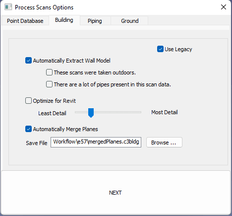
These scans were taken outdoors: Planes on the ground surface will not be extracted. If there is a substantial amount of terrain in the scan data, this option can significantly improve processing performance. Note that planes on the floor of an interior scan will also be excluded.
There are a lot of pipes present in this scan data: The algorithm will not attempt to extract planes on cylindrical objects. Use this setting when extracting pipes (Available only if the EdgeWise Plant and/or MEP modules are active), as cylindrical objects are represent better in EdgeWise pipe models. Checking this option will typically create a simpler and easier to navigate planar model.
Optimize for Revit: The level of detail of the planar model is set to the optimal setting for a workflow that involves eventually exporting walls and windows to Revit. This is equivalent to setting the Level of Detail to 3.
Level of Detail: The level of detail (1 to 10) represented in the planar data created during automated extraction. Sliding the slider all the left (1) will create a simpler planar model. Moving the slider all the way to the right (10), will create a more detailed model. A lower level of detail is generally more desirable when creating a Wall model for Revit, while a higher level of detail may be desirable in workflows that involve solid modeling in an application like 3DS Max, using the extracted planes as a reference.
Automatically Merge Planes: The planar data (.c3planes) for each scan will automatically merge in to a single Building model (.c3bldg). If unchecked, you will need to merge the .c3planes files using Merge Parts. We recommended to keep this option checked as only .c3bldg files are loadable into EdgeWise.
NOTE: Because merging Planes can be a very time-consuming process, we strongly recommend only merging 50 scans of data at a time.
Piping
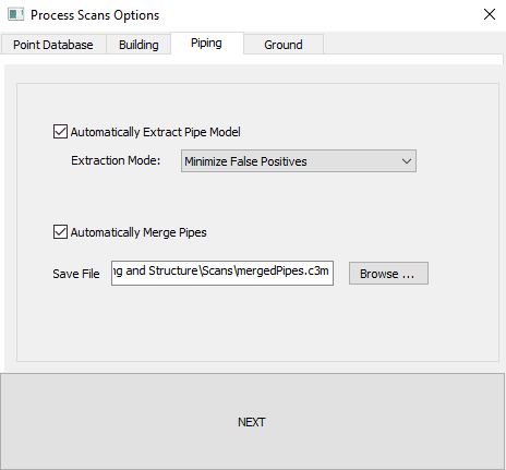
Automatically extracts pipe models with the Automatically Extract Pipe Model box selected.
Extraction Mode – chooses which piping automation algorithm EdgeWise uses during extraction. Minimize False Positives attempts to filter out more non-cylindrical items and other false positives. Maximize Number of Extractions will not filter out as many false positives, resulting in more pipe extractions, but possibly more false positive extractions. If your scanner has a low noise level and you there was good scan coverage of your project, you should choose Minimize False Positives. If your scanner has a high noise level or you have poor scan coverage of your project, you should instead choose Maximize Number of Extractions.
Automatically Merge Pipes – automatically merge the .c3pipes files and load the model into the scene. If you select this option and you are NOT creating a point database, a prompt will appear for a Point Database file. This Point Database file should contain at least all of the scans in the present process scans run. We recommend leaving this box checked. c3pipes files, on their own, cannot be loaded into EdgeWise; their merged counterpart, c3m files, can. It is best to let the algorithm do this up front.
Ground
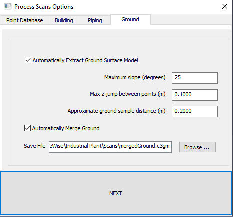
EdgeWise provides an automatic ground-seeking algorithm that starts at the lowest point within the scan and grows out to nearby ground points, following any moderately sloping surfaces upward (and downward). Three different parameters are adjustable within the Ground Surface module.
Maximum Slope – The steepest angle that the growing algorithm will use to be able to climb up while looking for ground points.
Max Z-Jump Between Points – The highest distance in the z-direction that the program can climb above existing ground points in order to find a new ground point.
Approximate Ground Sample Distance – The setting that determines the approximate ground sampling distance used to build a triangulated surface (TIN).