Search Knowledge Base by Keyword
Getting Started
The cable trays module inside of EdgeWise allows you to extract cable trays from the point database. This article will cover the different Alignment and Connection portions of the workflow for the Cable Trays module.
At this stage in the workflow you should have already used the Semi-Automated Extraction and QA tools. Now that your straight portions are extracted, you can begin the alignment and connection stage for your Cable Trays.
Alignment
Before you make elbow connections or transitions you may want to align your straight sections. Performing alignment is done with the Snapping tools found in the cable trays toolbar.
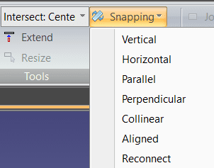
To use the snapping tools, you can select an individual cable tray (or multiple with Ctrl + left click) and use the options under the Snapping dropdown menu. While each snapping option has its use case, the most recommended is the Aligned snapping option. Simply select any cable trays you wish to be aligned to another, select Aligned under the Snapping dropdown menu, and select the reference cable tray (it should highlight blue when you hover your mouse). Once you left click, all of the selected cable trays will now be in alignment with the reference cable tray.
Elbow Connections
Whether or not you’ve chosen to use the snapping tools, you can make use of the Radius Elbow or Mitered Elbow automatic tools.
First, use ctrl-left click to select two straight cable tray sections. Don’t worry about transitions within elbow connections, as they will be inserted automatically. Lastly, click Radius Elbow or Mitered Elbow to insert the correct elbow.
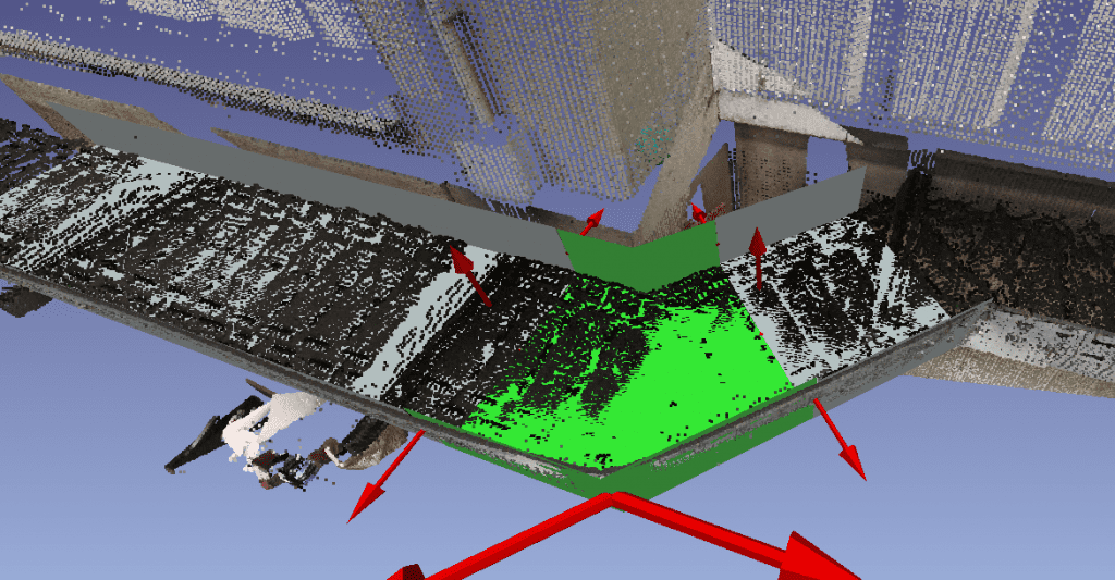
If you need to adjust the elbow to the proper fit, take advantage of the red adjustment arrows.
Joins and Reducers
There are two methods for connecting straight elements; join and reducer.
To create a straight join between elements, first select the two elements to be connected. Achieve this by either ctrl + left clicking each element OR shift + left clicking to make a selection box. Next, click the Join button in the Tools portion of the Cable Trays tab. Keep in mind, to create a straight connection between elements they must be of the same standard size and type. Additionally the elements must be roughly parallel to each other (within 15 degrees).
To connect two cable trays via a reducer element, first select the two elements using the same selection methods explained above. Next, click the Transition button in the Tools area of the Cable Trays tab. Keep in mind, when creating the transition, the axes between the cable tray elements are forced to be parallel (if necessary).
Proceed to the next step in the workflow – Exports.