Search Knowledge Base by Keyword
Getting Started
This article will cover the various Pipe Model Display settings. To access these options, right click on your pipe model in the Model Selection Pane and click Model Display. Alternatively, select your pipe model in the Model Selection Pane, click on the Piping tab in the ribbon, then click Model Display.
Model Display
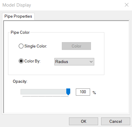
Coloring
Pipe models can have their color effected in a variety of ways – by radius, coverage, RMSE (Root Mean Squared Error), layer, approved parts, and approved chain. To color your pipe model in any of these ways ensure the Color by: radio button is filled. Next, select the appropriate coloring scheme from the adjacent drop box.
Coloring – Radius Mode
Radius Mode colors pipes based on their radius. Pipes with a radius between 0 meters and 0.25 meters will appear between red and yellow. If a pipe’s radius is between 0.25 to 0.5 meters, it will appear between yellow and green. Pipes with a radius from 0.5 to 0.75 will appear between green and cyan. Lastly, pipes with a radius from 0.75 to 1.0 meters will appear between cyan and blue.
Coloring – Coverage Mode
Coverage Mode colors pipes based on their coverage – the percentage of the pipe’s surface area that was scanned. Pipes with information from only one scanner can have, at most, 50% coverage (no data for the back side). Pipes with information from multiple angles can achieve 100% coverage. If a pipe’s coverage is between 0-25%, it will appear between red and yellow. Pipes with 25-50% coverage will appear between yellow and green. Pipes with 50-75% coverage will appear between green and cyan. If a pipe’s coverage is between 75-100%, it will appear between cyan and blue.
Coloring RMSE Mode
RMSE Mode colors pipes based on their RMSE value. Think of RMSE value as the amount of noise. Pipes with an RMSE value between infinity and 0.007 will appear between red and yellow. If a pipe’s RMSE value is between 0.007 and 0.006 will appear between yellow and green. Pipes with RMSE value between 0.006 and 0.005 will appear between green and cyan. Pipes with a RMSE value between 0.005 and 0.0 will appear between cyan and blue.
Coloring – Layer Mode
Layer Mode colors pipes according to which layer a pipe belongs to.
Coloring – Approved Parts
Approved Parts colors pipes based on their approval status in the Part Info Smartsheet (Q). When you first switch to this color mode, your model may appear entirely red. This simply means no pipe parts have been approved yet. Navigate to the Piping tab in the ribbon, click Smartsheet, then Part Info Smartsheet (Q). You will notice an Approved column. When a pipe element has a Yes in this column, it will appear green while this color scheme is active.
Coloring – Approved Chain
Approved Chain colors pipes based on their approval status in the Chain Info Smartsheet (I). When you first switch to this color mode, your model may appear entirely red. This simply means no pipe chains have been approved yet. Navigate to the Piping tab in the ribbon, click Smartsheet, then Chain Info Smartsheet (I). You will notice an Approved column. When a pipe chain has a Yes in this column, it will appear green while this color scheme is active.
Alternatively, you can color your pipe model by a single color of your choosing. Simply check the Single Color: radio button and select a color.
Opacity
This sets the opacity of the active pipe model—0 is totally transparent, 100 is totally opaque.
Color Scale Bar

The color scale bar is a handy tool that is present whenever a pipe model is the active layer. You can use this as a quick reference to give an approximate value to the color of a given pipe. Enable or disable the color scale bar from the Options menu in the top right corner of the main window.
For more information regarding piping tools, start with this article.