Search Knowledge Base by Keyword
Getting Started
This article will cover the Semi-Automated Extraction and Connection portions of the piping workflow. To begin this workflow, ensure you have a point database model, and piping model for your project already created, QA’ed, Cleaned, and opened.
The Semi-Automated Extraction and Connection tools are designed to supplement the full automation from Process Scans. However, there are some cases where you may only need to extract a small portion of the entire point cloud. There are other cases where QA would take longer than starting from scratch. In these cases, you may start with Semi-Automated Extraction instead of starting with full automation. First, you only need to process the point database. Then, in the File tab, click on Blank Model > New Pipe Model. From here, reference the rest of this article to begin your workflow.
Extraction
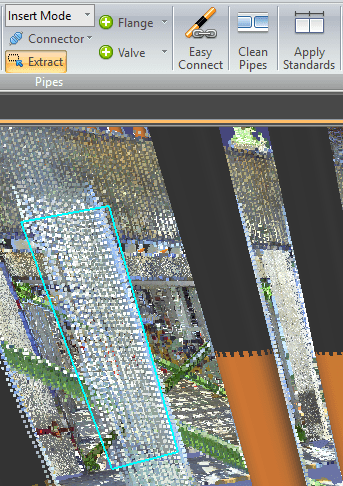
To Extract a pipe, select the Extract (X) tool in the EdgeWise Piping tab. Now left click to start your selection box and continue left clicking around your point cloud data. When your polygon surrounds your desired pipe, double click to finish the selection.
You can edit the cylinder further by using the Edit (E) tool in the Piping Tab. Select the Edit tool, than select a cylinder in the 3D view. White orbs should appear on the endpoints. Drag these orbs to extend or shorten the pipe. Additionally, you can use the Move (D) tool to anchor the opposite endpoint and move the selected endpoint in free form space.
Connection
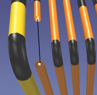
Connecting pipes is as simple as connecting the dots. First, select the Connector (C) tool. Next, select one pipe end point and then select the next pipe endpoint, as seen below in Fig 2. EdgeWise will place a straight connector or an elbow.
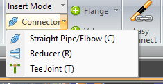
If you select the drop down arrow on the Connection tool, you can select a Reducer (R) or a Tee Joint (T) . Reducers work the same way as Straight Pipes or Elbows. However, ensure you insert reducers between pipes that are actually different sizes or you may be missing this connection within your deliverable.
Inserting a Tee Connection
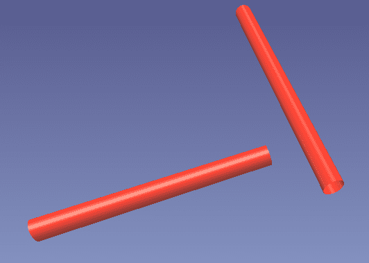
Tee connections are the most unique to insert out of all the connection types. Let’s say we have a situation like this:
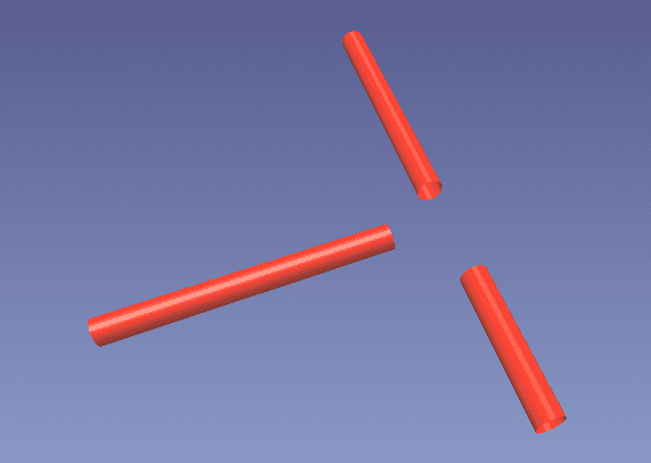
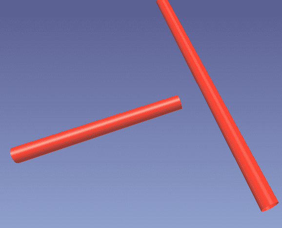
A Tee joint needs to have a connection between the endpoint of the branch pipe, and the center of the main pipe. There are two ways to do this in our example. First, we could just delete one of the main pipe sections, and Edit (E) the other and drag it along until there is enough space for a Tee.
Alternatively, we could insert a straight connection between both main pipe pieces and then clean the pipe.
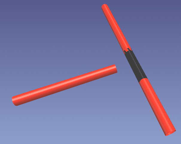
Remember – You can’t have a connection intersect within another connection. This is why we must ‘clean’ in the second method. The tee joint can’t connect to the straight connector.
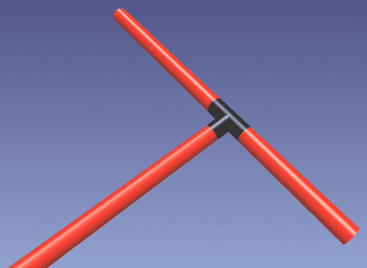
Now, in either method, you can select our Tee Joint from the drop down menu or press T on your keyboard. Next, click the white dot endpoint on the branch pipe, and click the center of the main pipe. This will insert our tee connection, as seen below.
The next step in the workflow is Clean Pipes and Apply Standards.